Offshore Structures — General Introduction
A comprehensive overview of offshore platform types, design frameworks, and project lifecycle in the modern deepwater era.
1. Historical Context and Evolution
Offshore structural engineering emerged in the 1950s with the first oil and gas platforms in the Gulf of Mexico and the North Sea. Early designs were relatively simple fixed structures in shallow water (less than 100 meters). Today, the industry operates platforms at depths exceeding 3,000 meters, with designs that incorporate advanced materials, digital twin technology, and autonomous monitoring systems.
The evolution reflects increasing water depths, environmental challenges, and economic pressures. Platforms that took years to design now benefit from parametric modeling and AI-assisted optimization. Modern designs must also consider decommissioning and circular economy principles—a significant departure from the "build and abandon" mentality of earlier decades.
2. Classification of Offshore Platform Types
Fixed Platforms
Jacket Structures are the most common fixed platforms, consisting of a steel lattice framework (jacket) pinned or grouted to the seafloor via piles. Jackets typically comprise four leg groups, horizontal and diagonal bracing members, and a topside (deck) structure supporting drilling, production, and living quarters. Water depth range: 20–500 meters (economically viable to 600 m with deepwater extensions).
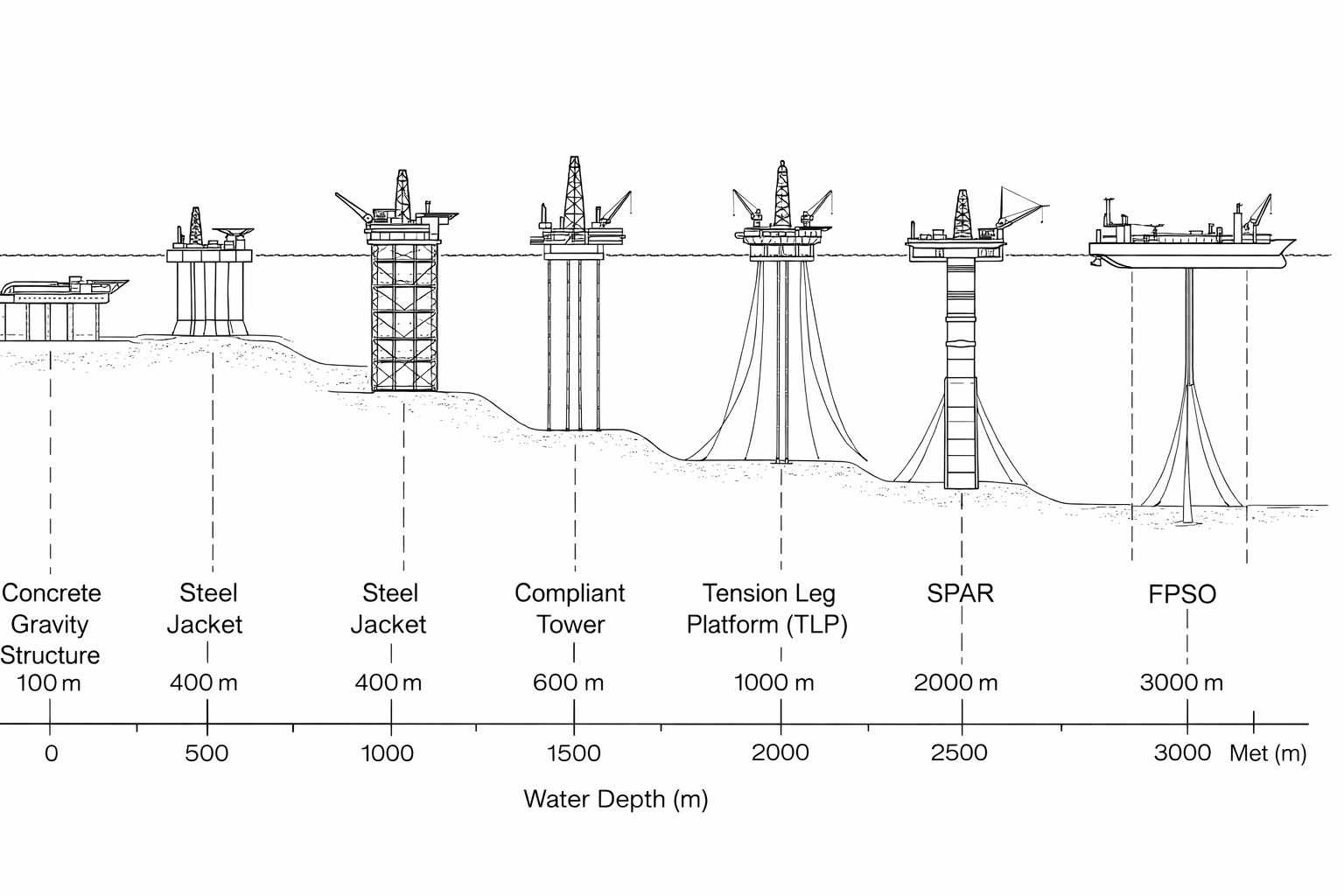
Gravity Based Structures (GBS) rely on self-weight for stability. A large reinforced concrete base sits directly on the seafloor; no piling is needed. Typical for harsh North Sea conditions, ice-infested waters, and seismic zones. Water depth: 150–400 meters. Advantages include no pile driving (quieter, less environmental impact) and massive storage capacity for crude oil.
Floating Structures
FPSO (Floating Production, Storage, and Offloading) vessels are ship-shaped hulls that produce, process, and store hydrocarbons, then offload to shuttle tankers or via subsea pipelines. Flexible and cost-effective for development, FPSOs dominate deepwater fields in Africa, Southeast Asia, and Brazil. Typical capacity: 50,000–300,000 barrels per day. Water depth: 100–3,000 meters.
Spars are large-diameter cylindrical structures with a small waterplane area, designed for minimal motion in waves. A subsurface buoyancy column provides restoring force; mooring lines tether the spar to the seafloor. Used for deepwater production (1,000–3,000 m). Advantages: excellent motion characteristics, suitable for tieback developments. Disadvantages: complex design, higher cost.
Tension Leg Platforms (TLPs) combine a floating hull with vertical tendons in tension. Buoyancy exceeds weight; mooring tension prevents upward motion. Excellent for heave mitigation in harsh environments. Water depth: 500–2,000 meters. Used in the Gulf of Mexico, North Sea, and Southeast Asia.
Semi-submersibles (Semi-subs) have multiple pontoons and vertical columns, with hulls partially submerged for stability and reduced wave loading. Versatile for drilling, production, and construction support. Water depth: 100–3,000 meters. Superior station-keeping relative to conventional ships, yet less motion-sensitive than Spars.
3. Water Depth vs. Platform Type Selection
| Water Depth | Suitable Platform Types | Typical Applications | Key Challenges |
|---|---|---|---|
| Shallow (20–100 m) | Jacket, Caisson, GBS | Conventional development | Wave/wind loading, access in storms |
| Intermediate (100–400 m) | Jacket, Semi-sub, TLP, GBS | Oil & gas, drilling | Fatigue, mooring, installation logistics |
| Deep (400–1500 m) | FPSO, Spar, Semi-sub, TLP | Production, tieback to shore | Subsea infrastructure, umbilical design |
| Ultra-deep (>1500 m) | FPSO, Spar, Subsea systems | Exploration, niche production | Cost, subsea intervention, mooring |
4. Design Life and Service Planning
Design life is the period for which a structure is intended to operate safely with proper maintenance. Typical values:
- Jackets: 20–30 years (extendable to 40+ with life extension projects)
- GBS: 25–40 years
- Floating units: 20–25 years initial, with upgrade and refurbishment cycles
Beyond design life, structures undergo evaluation for fitness-for-service (FFS) or life extension. Modern data acquisition—real-time monitoring via IoT sensors—enables condition-based maintenance and extended operational windows. Paradoxically, some aging platforms remain in service 20–30 years past their design life due to economic viability and deferred replacement capital costs.
5. Regulatory Framework and Standards
Offshore design is governed by prescriptive and performance-based standards. Key frameworks include:
- API RP 2A-WSD (2014): American Petroleum Institute standard for fixed structures (jackets, GBS). Covers design, fabrication, and installation; widely adopted globally.
- ISO 19902:2020: International standard for fixed offshore structures. Performance-based, emphasizes reliability and consequence-dependent design factors.
- DNVGL-RP-C203 (Class Rules for Ships): Det Norske Veritas & GL rules for floating units (FPSO, Spar, Semi-sub).
- API RP 2GEO (2011): Geotechnical engineering standard for piles and foundations.
- DNVGL-RP-B401: Rules for submarine pipeline systems.
National authorities add additional requirements. UK Health and Safety Executive (HSE), Norwegian Petroleum Safety Authority (PSA), and other regimes impose stricter safety factors and consequence-based design in some jurisdictions. Modern projects increasingly adopt quantitative risk assessment (QRA) and probabilistic design methods alongside deterministic checks.
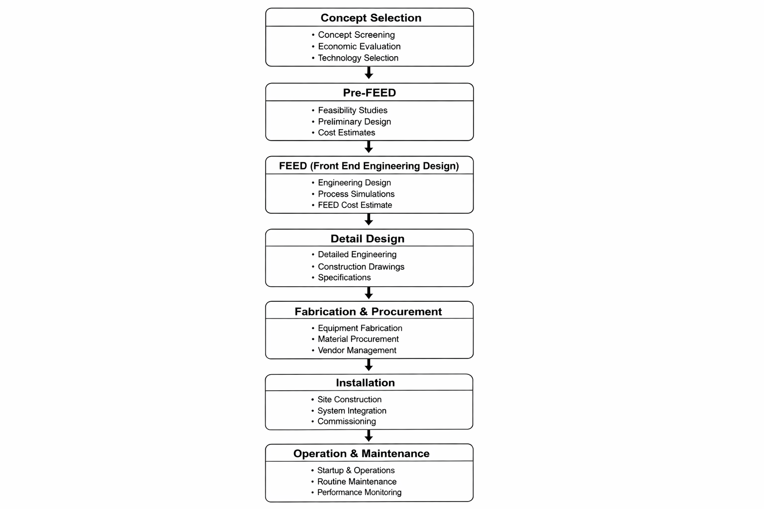
6. Project Phases and Lifecycle
- FEED (Front-End Engineering & Design): 6–18 months. Concept selection, basic design, feasibility studies, cost and schedule estimation, regulatory pre-engagement.
- Detailed Design (EPC Phase): 18–36 months. Full-scale FEM analysis, code compliance verification, drawings for fabrication, vendor data reviews.
- Procurement & Fabrication: 24–48 months. Ordering of steels, subsystems; building and testing in fabrication yards, NDT inspections.
- Installation & Commissioning: 6–18 months. Transporting structures, seafloor preparation, pile driving or gravity setting, topside integration, pre-service testing, final certifications.
- Operations & Maintenance: 20–40 years. In-service inspections, fatigue monitoring, risk assessments, repair campaigns.
- Decommissioning: 2–5 years. Removal of structures, recycling of materials, environmental restoration, regulatory closure.
7. Construction Overview
Modern offshore construction integrates modularization, factory assembly, and lean principles to reduce schedule and cost. Jacket legs, deck modules, and subsea infrastructure are often built in geographically dispersed yards, then transported and integrated on-location. Heavy-lift vessels capable of hoisting 10,000+ metric tons enable single-lift installation. Alternatives include float-over mating (combining jacket and deck offshore) and topsides-first integration (setting the deck first, then grouting the jacket around it).
Subsea infrastructure—manifolds, trees, control cabins, flowlines, and risers—is increasingly integrated into a single template or modular package, reducing field complexity. Autonomous underwater vehicles (AUVs) for survey and inspection, subsea welding systems, and ROV interventions represent the modern toolkit.
8. Deepwater and Ultra-Deepwater Developments
Advances in the last 15 years have pushed the economic boundary of offshore development into ultra-deepwater (2,000–3,000 m+). Guyana, Equatorial Guinea, and the Gulf of Mexico host some of the world's largest recent discoveries at depths that were considered uneconomic a decade ago. Key enablers:
- FPSO and Spar designs optimized for cost reduction and scalability
- Tieback architecture reducing subsea infrastructure footprint
- Multiplexed umbilicals and wet-tree completions
- Modular flowlines and flexible riser systems
- AI-driven maintenance prediction and lifecycle cost optimization
Key Design Principles
- Functional Requirements: Safe production, personnel safety, environmental protection, and economic viability form the foundation of every design.
- Robustness Over Precision: Designs must tolerate uncertainties in loading, material properties, and construction tolerances. Conservative assumptions protect against unknown-unknowns.
- Modularity and Flexibility: Modular designs allow for upgrades, life extension, and decommissioning without global redesign.
- Regulatory Compliance and Risk Management: Codes are minimum baselines. Project-specific risk assessments often demand higher safety margins.
- Lifecycle Perspective: Initial design decisions impact fabrication, installation, operations, and final decommissioning—optimize for the total cost, not the design phase alone.
9. Typical Project Phases Summary
| Phase | Duration | Key Deliverables | Main Stakeholders |
|---|---|---|---|
| FEED | 6–18 mo | Concept design, cost estimate, regulatory approval path | Operator, consultant, regulator |
| Detailed Design | 18–36 mo | FEA, P&IDs, fabrication drawings, specification packages | Engineering contractor, vendor |
| Procurement | 12–24 mo | Vendor contracts, purchase orders, material certifications | Supply chain, quality assurance |
| Fabrication | 24–48 mo | Assembled jackets, modules, NDT reports, testing | Fabrication yards, inspectors |
| Installation | 6–18 mo | As-built records, pile driving logs, commissioning reports | Installation contractor, offshore crew |
Advertisement
Educational use only. All tools and course content on SmartUtilz are for informational and study purposes. Results must be independently verified by a qualified engineer before use in any design or safety-critical application. Read full disclaimer →